In principle, one could determine the relationship of the output voltage of the slow antenna to the vertical electric field by determining the gain of the antenna's charge amplifier, the area of the sensor plate, and the effective gain factor of the antenna. The first two quantities are readily obtained. However, it is very difficult to directly determine the antenna's geometrical gain factor since the electric field lines wrap around the grounded top hat and connect to the sensor plate in a complex way. The way to circumvent this difficulty is to calibrate another electric field antenna which has a much simpler geometrical arrangement and then calibrate the slow antenna by intercomparing data between the systems. This process is described below.
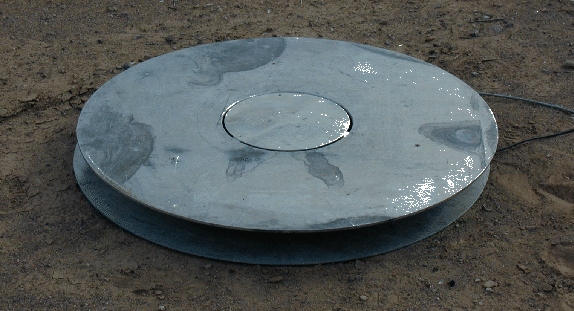
Figure B.5 shows a picture of Marx Brook's calibrator. This calibrator was used to calibrate the slow antenna in all of the field programs described in this dissertation. The ground ``plane'' surrounding the sensor in Figure B.5 ensures that the electric field will be undistorted above the sensor. Consequently, the gain factor of the calibrator antenna is equal to 1.
 |
The simplest means of calibrating the calibrator was to apply a square wave of known amplitude to a metallic plate spaced precisely 10 cm above the calibrator. By measuring the output voltage amplitude for a known electric field change amplitude, the electric field change of sferics could be determined from the change in output voltage (assuming no saturation).
Once the conversion factor between volts and volts/meter was known for the calibrator, the calibrator was placed outside in a flat area free from nearby obstructions. The electric field changes of sferic waveforms was recorded and compared with the voltage changes simultaneously observed on the slow antenna. The conversion factor of volts to volts/meter for the slow antenna could then be easily obtained. This intercomparison was repeated for the different gain settings of the slow antenna.