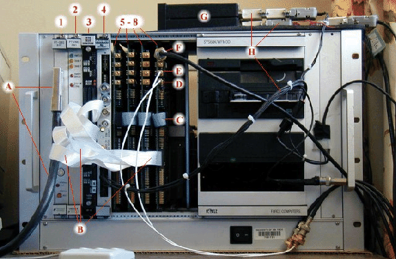
The data acquisition system was composed of a VME-based digitizing and processing system linked to a Sun IPC host computer. A photograph of the VME system is shown in Figure A.1. The VME boards are numbered in the figure and are described in Table A.1. The digitizer cards were specially designed for the system by W. Rison. The data acquisition software was developed by the author.
 |
| ||||||||||||||||||||||||||||||||||||||||||
Cable ``A'' in Figure A.1 links the VME system to the host Sun IPC unit. Prior to acquiring data, a program is run on the Sun which downloads an executable program to the DSP board (3) in the VME system. The program first resets the A/D boards and then continuously processes data received from the boards through the cables marked with ``B'' in Figure A.1. Cable ``C'' interconnects the A/D boards and allows a single chip on a ``master board'' to control and synchronize the data sampling on the other boards. A jumper on the master board allows one to configure the sampling rate at either 500 kHz or 1 MHz. Each card can be jumpered to sample four 8-bit channels simultaneously, or one 8-bit and two 12-bit channels. The former has been the preferred mode for sampling interferometer phase data while the latter is used for sampling log-RF (8-bit) and sferics data (12-bit).
All four A/D boards are utilized when interferometer data is acquired. However, when the picture in Figure A.1 was taken, only sferics were being acquired. Log-RF data was input into the 8-bit channel F while 12-bit slow and fast antenna data were input into the 12-bit channels E and D respectively.
The black box at top (G) is the Horita unit (viewed side on) which is used for normal-speed video timing, as described in Appendix B.4.1. GPS timing information is input into the Horita unit and the VME system via the cables marked with ``H''.