Prior to the sprite campaign conducted at Langmuir Laboratory in 1997,
normal-speed video timing was obtained by placing one or more LEDs
within the field of view and connecting the LED(s) to a calibrated
GPS-based signal(s). The UTC time in hours, minutes, and seconds was
either placed directly onto the video by a VCR or was added to the
video in post-processing. The time placed on video was accurate to
only a few tenths of a second. Sub-field accuracy (![]() 17 ms) was
obtained by estimating the time of the LED transition by implementing
a procedure similar to that detailed in B.4.2.
17 ms) was
obtained by estimating the time of the LED transition by implementing
a procedure similar to that detailed in B.4.2.
A new technique was employed in 1997 to obtain normal-speed video timing. Horita GPT-50 units were used to place GPS information directly onto the video signals. The Horita units were specially modified by the manufacturer to insert a white vertical stripe onto the left side of the video image in response to a GPS-based pulse.
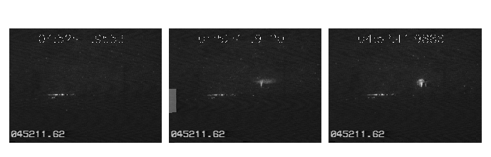 |
Figure B.2 shows 3 video fields extracted from a
normal-speed video sequence around the time of a sprite event. The
Horita GPT-50 inserted a vertical stripe at the left side of the
middle image. The top of the stripe corresponds with the exact moment
in which the onset of a second occurred according to GPS timing. By
examining where in the video field the top of the stripe appears, one
could theoretically determine the exact timing of the video to within
the time period required to scan one line (![]() 100
100 ![]() s). In
practice, however, such precision has not been achieved since the
output timing characteristics of the video camera were not known
precisely.
s). In
practice, however, such precision has not been achieved since the
output timing characteristics of the video camera were not known
precisely.
An image field is not converted to a video signal until after the
light integration period is over. Consequently, the vertical stripe
will always appear in a frame prior to the one in which the transition
actually takes place. The length of time it takes to output a video
field as a video signal after the start of light-integration is always
at least the duration of a video field; ![]() ms
ms![]() = 16.7 ms.
However, there are additional delays on the order of a few
milliseconds. To determine the actual delay, light from return
strokes within the camera's field of view was used. Because the light
output from a lightning discharge increases many fold during the
return stroke process, return strokes are easy to detect on video.
The actual time of the return strokes could be determined precisely
from the recorded sferics data. By examining many return strokes, the
delay for the placement of the vertical stripe into a video image
relative to the start time of light integration for the video image
was determined to be 20 ms with an uncertainty of approximately 1 ms.
Such precision was adequate for most normal-speed sprite observations.
= 16.7 ms.
However, there are additional delays on the order of a few
milliseconds. To determine the actual delay, light from return
strokes within the camera's field of view was used. Because the light
output from a lightning discharge increases many fold during the
return stroke process, return strokes are easy to detect on video.
The actual time of the return strokes could be determined precisely
from the recorded sferics data. By examining many return strokes, the
delay for the placement of the vertical stripe into a video image
relative to the start time of light integration for the video image
was determined to be 20 ms with an uncertainty of approximately 1 ms.
Such precision was adequate for most normal-speed sprite observations.