The orientation of the normal-speed camera was determined by using stars within the field of view. The actual azimuths and elevations of stars can be calculated for any location on the globe once the date and time of the observation are known.
Prior to 1998, the camera orientation was determined by guessing an azimuth, elevation, and rotation angle and then outputting a stellar image from a software program called ``Sky Map'' for this guess. The stellar image was then rescaled so that the star pattern had the same 2-dimensional size as the actual image and the two images were then digitally combined so that the stars overlapped. If there was no significant rotation angle, then the center azimuth and elevation of the image could be obtained directly from this procedure as well as the field of view (if it wasn't already known). However, if there was a significant rotation angle, multiple such image overlays might have to be attempted until both the angle and the proper image resizing could be accurately determined. This procedure was very tedious and could easily take several hours per camera orientation.
In early 1998, Christopher Barrington-Leigh of Stanford University adapted some astronomical routines to Matlab for the purpose of predicting the azimuth and elevation of stars for a given location, date, and time. These routines were adapted to IDL by the author and were integrated into the author's IDL sprite analysis software. The routines also incorporated refractive corrections developed and written by the author (see Section B.5).
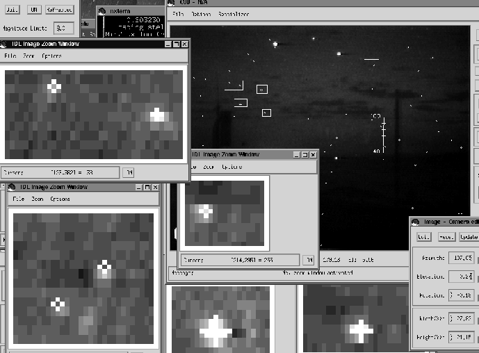 |
Figure B.1 shows how the camera orientation is determined. A normal-speed video image is displayed within the large window in the upper right. The image is the average of several frames. By averaging frames, the signal to noise level is improved. This results in more stars being visible as well as better highlighting of any cloud boundaries.
The white crosses on the image are the calculated star positions according to the camera orientation settings, camera field of view, camera location, date, and time. The size of a given cross is an indication of the apparent brightness of the star, with bigger crosses corresponding to brighter stars. The goal of the star alignment procedure is to adjust the camera orientation settings (and field of view settings, if not already set) until an optimal alignment is achieved between the calculated star positions and actual star positions. Once the optimal alignment is found, the camera settings were stored in a configuration file for future use. The same camera settings were also used for other video sequences if the camera was pointing in the same direction with the same lens settings.
The error in the final azimuth and elevation of the camera orientation
was sub-pixel if there were many stars in the field of view, but was
more typically on the order of a pixel. The angular size of a pixel
depended on the lens, but was ![]() 0.04
0.04![]() in width and
height for the 25 mm lens which was used for most of the normal-speed
sprite video shown in this dissertation.
in width and
height for the 25 mm lens which was used for most of the normal-speed
sprite video shown in this dissertation.