The third sprite event occurred at 01:51:02 UT. The video sequence of the sprite event is shown in Figure 3.13. The sprite cluster was the brightest of the night. The heads of the sprites saturated the first frame. Tendrils were readily visible and numerous below the sprite heads. Light integration for the first frame began at 01:51:02.748 UT and lasted for 16.7 ms.
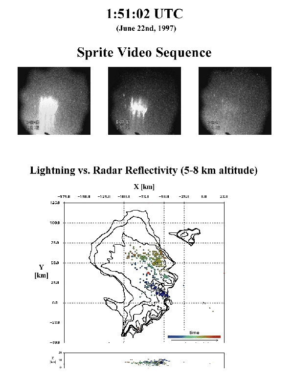 |
Figure 3.13 shows that the flash originated in
a convective cell between the cells where flashes 01:42:57 and
01:47:52 UT originated. The temporal development of the flash was
very similar to that of the 01:42:57 UT flash, as
Figures 3.14 and 3.15
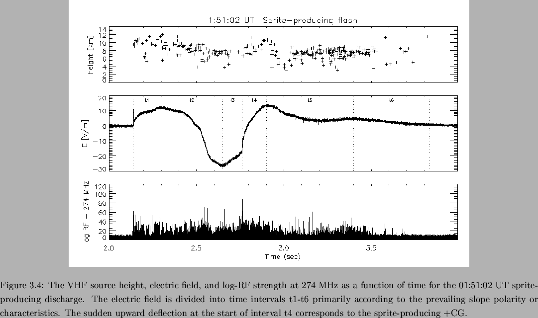
show. The flash developed vertically as a bilevel IC in time interval
t1. The negative leaders in the upper level then propagated
horizontally outward away from the slow antenna in interval t2. The
flash covered a horizontal distance of ![]() 55 km in
55 km in ![]() 0.35 s
during interval t2. The average speed of development was
0.35 s
during interval t2. The average speed of development was
![]() 1.6
1.6![]() 10
10![]() m/s. This speed is consistent with that
normally observed for negative leaders, as discussed in
Section 3.6.
m/s. This speed is consistent with that
normally observed for negative leaders, as discussed in
Section 3.6.
The electric field deflected dramatically upward at the beginning of interval t3 and maintained a constant slope throughout (see Figure 3.14). This is difficult to understand based solely on the negative leader activity, which produced only a few data points primarily near the start of the interval and on the upper right quadrant of the discharge.
Conceptually, an upward deflection of the electric field would be
produced by the onset of positive leader activity which was
propagating downwards or away from the observation site. It is
interesting to note that a single data point in interval t3 appeared
at 4-5 km altitude almost directly above the +CG location of interval
t4. If a positive leader was propagating uniformly downwards from
![]() 7.5 km altitude over the
7.5 km altitude over the ![]() 0.11 s duration of interval t3,
the average downward propagation speed would be
0.11 s duration of interval t3,
the average downward propagation speed would be
![]() 6.8
6.8![]() 10
10![]() m/s. The progression speed would be greater
if the leader took a tortuous path to ground, as leaders often do. A
positive leader may also be responsible for the less dramatic electric
field increase during time interval t3 of the 01:42:57 UT flash
(Figure 3.4).
m/s. The progression speed would be greater
if the leader took a tortuous path to ground, as leaders often do. A
positive leader may also be responsible for the less dramatic electric
field increase during time interval t3 of the 01:42:57 UT flash
(Figure 3.4).
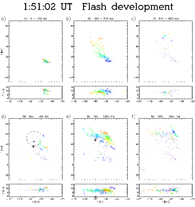 |
A 61.3 kA +CG occurred at 01:51:02.762 UT and marks the start of interval t4. The brightness of the sprite cluster in Figure 3.13 makes it difficult to locate individual sprites. The azimuth extent of the sprite cluster on video was obtained and the heights of the sprites at each azimuth extrema were used to estimate the distance to the sprite cluster ``center''. The sprite cluster is drawn as a circle in Figure 3.15d.
The actual shape of the sprite cluster is unknown for the ``back'' side, since it is obscured by the foreground sprites. Regardless, the portion of the sprite cluster which can be seen appears to be associated with the periphery of the discharge, as with the previous sprite events. Also like the previous sprite events, the +CG occurs on the side of the sprite cluster in the opposite direction of the preceeding negative leader propagation. Not surprisingly, the LDAR-indicated charge center appears to be a better, if still imperfect, approximation of the sprite cluster plan location than the CG.
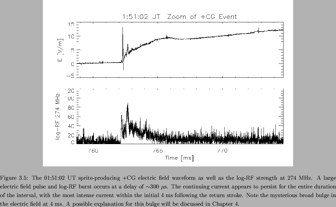
The de-drooped fast electric field waveform for the +CG stroke is
shown in Figure 3.16 along with the log-RF
strength. The static electric field grew most rapidly during the
initial ![]() 300
300 ![]() s. A substantial electric field change
occurred at
s. A substantial electric field change
occurred at ![]() 300
300 ![]() s and is accompanied by intense log-RF at
274 MHz. This field change appearred to have been inductive in nature
as it does not produce much of a static field change. The static
electric field continued to increase dramatically for
s and is accompanied by intense log-RF at
274 MHz. This field change appearred to have been inductive in nature
as it does not produce much of a static field change. The static
electric field continued to increase dramatically for ![]() 4 ms, at
which point it increased at a slower rate. The bulge at
4 ms, at
which point it increased at a slower rate. The bulge at ![]() 4 ms
may be due to current flowing in the sprite itself. The presence of
significant sprite currents will be discussed in Chapter 4.
4 ms
may be due to current flowing in the sprite itself. The presence of
significant sprite currents will be discussed in Chapter 4.
The flash activity after interval t4 was arbitrarily divided into intervals t5 and t6. As was observed for previous sprite-producing flashes, the majority of VHF sources observed below 6 km altitude appeared after the sprite event. What is particularly interesting about interval t5 is that there was a tight cluster of 3 -CG strokes which appeared below the horizontally extensive discharge.
It is conceivable that the -CG strokes were produced when one or more
negative leaders from the sprite-producing flash struck the ground.
However, it is far more likely that they were part of a separate
discharge initiated by the +CG. From Table 3.1, the
+CG produced a charge moment change which at 4 ms post-return stroke
delay was ![]() 20 times larger than normally observed for -CGs. The
electric field beneath the discharge would also have been similarly
enhanced, with the actual enhancement factor dependent on discharge
geometry.
20 times larger than normally observed for -CGs. The
electric field beneath the discharge would also have been similarly
enhanced, with the actual enhancement factor dependent on discharge
geometry.
The electric field at the top of a tall metallic structure such as a
radio and communications tower might have exceeded the electrical
breakdown strength of air while subjected to the strong electric
field. This could have resulted in the formation of an
upward-developing positive leader. This process would be essentially
identical to that of ordinary triggered lightning, with the only
difference being that the conductor is fixed within a very rapidly
growing field (![]() milliseconds) as opposed to rapidly extending
(
milliseconds) as opposed to rapidly extending
(![]() seconds) through a fixed electric field. It is well known that
ordinary triggered lightning can produce return strokes 10's or 100's
of milliseconds after trigger initiation.
seconds) through a fixed electric field. It is well known that
ordinary triggered lightning can produce return strokes 10's or 100's
of milliseconds after trigger initiation.
The -CG strokes were in the same location as the -CG observed for the previous sprite-producing discharge. These -CGs were in the vicinity of Florida Hills, which is slightly elevated above the surrounding terrain and is in a strategic position for radio broadcasts to both Orlando and Daytona Beach. Whether or not radio towers were located at the -CG strike positions is not known by the author, but this will be examined in the future.
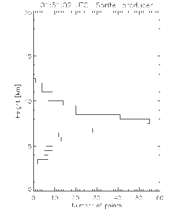
The height distribution of VHF sources for the 01:51:02 UT flash is
shown in Figure 3.17. The density peak at
7-8 km altitude corresponded to the average charge removal height of
the +CG. Assuming an average height of ![]() 7.5 km altitude and the
LDAR-indicated charge moment change in Table 3.1, the
charge transferred to ground (-Z direction) would have been 28 C at
1 ms and 52 C at 4 ms. The average current to ground for these
intervals would have been 28 kA and 13 kA respectively.
7.5 km altitude and the
LDAR-indicated charge moment change in Table 3.1, the
charge transferred to ground (-Z direction) would have been 28 C at
1 ms and 52 C at 4 ms. The average current to ground for these
intervals would have been 28 kA and 13 kA respectively.
 |